

STAGE 2: TECHNOLOGY ASSESSMENT
Building upon the Technology Qualification basis defined in the first stage, the second stage comprises a detailed assessment of the technology and principal uncertainties associated with its use, in order to focus the definition of qualification activities in Stage 3. The assessment commences with decomposition of the system into discernible elements, followed by two parallel activities; Technology Maturity Assessment and Risk Assessment.
To illustrate the Technology Assessment process, a generic mooring connector is used as an example of a component which is used to join mooring line elements together or connect lines to anchors and top-side equipment
SYSTEM DECOMPOSITION
Decomposition analysis can be used to determine which element(s) of the technology are novel, or new to an application. This is carried out to classify where the element fits into the system, subsystem or component hierarchy. According to NASA in Chapter 2 The Systems Engineering (SE) Process, these terms are defined as:
- System - An integrated set of elements that accomplish a defined objective.
- Sub-system - A system in its own right, except it normally will not provide a useful function on its own, it must be integrated with other subsystems (or systems) to make a system.
- Components - Elements that make up a subsystem or system.
The functions, operational modes, processes and project phases of each element are then identified in order to assist in the determination of technology maturity. Typically, a combination of approaches are used in the technology decomposition process, including structural system decomposition (SSD) and functional system decomposition (FSD).
SSD is used to decompose the technology from the highest (system) level into lower levels (i.e., component/sub-component level) until a single maturity level can be assigned to a tangible hardware (or software) element. Similarly, FSD starts with the highest (system) level and progressively works down through the system hierarchy levels until all functions (or sub-functions) and structures, human-machine interactions as well as team roles and responsibilities are assigned to technology elements. For each decomposed element, the usage, operating modes and integration issues are documented. FSD is more suited to procedural, or software-driven technologies (i.e., those which feature user-input).
It is important that element functionalities are considered holistically during all project phases (i.e., transportation, installation, operation and decommissioning). For example, a sealing element needs to function during all life phases - not just operation, in order to prevent lubricant leakage. The conditions in each of the project phases impart different requirements or physical boundary conditions that affect seal function.
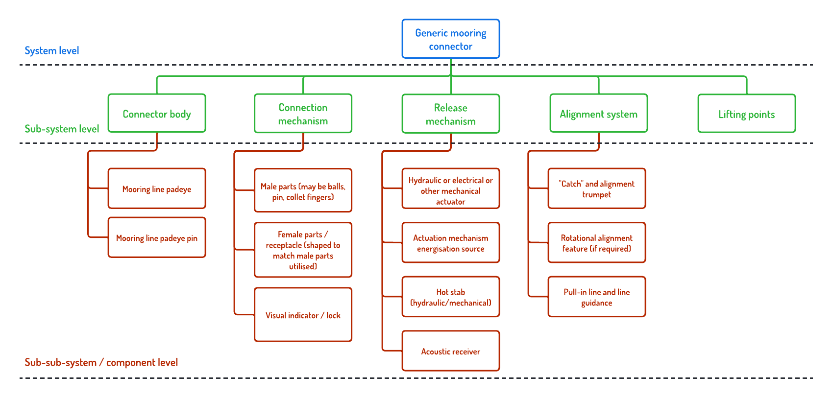
System Decomposition Example: Generic Mooring Connector
|
Decomposition of a generic connector into principal elements is provided in the diagram below, with functions for each element, at each system level, listed in the table below. |
|
| System | Function | Sub-system | Function | Sub-sub-system/component | Function |
| Mooring connector | Remotely connect two parts of mooring system for long term mooring | Connector body | House/support other sub-systems | Mooring line padeye | Provide connection to mooring line |
| Provide mooring tensile load path | Mooring line padeye pin | Provide connection to mooring line | |||
| Resist out-of-plane forces/moments | N/A | N/A | |||
| Connection mechanism | Make primary load connection between two ends of full system | Male parts (may be balls, pin, collet fingers) | Transmit mooring load | ||
| Generate connection preload if selected function | |||||
| Allow system disconnection when actuated by release mechanism/systems | Female parts / receptacle (shaped to match male parts utilised) | Transmit mooring load | |||
| Provide feedback that confirms successful hook-up | Visual indicator / lock | Passive locking feedback | |||
| Release mechanism | Provide actuation to connection mechanism to allow release | Hydraulic or electrical or other mechanical actuator | Provide force or movement to release connection mechanism | ||
| Actuation mechanism energisation source (internal or external power source or store e.g. hydraulic power unit or accumulator or electric power supply or battery) | Provide energy to release actuator | ||||
| Provide means to over-ride primary release method in event of failure | Hot stab (hydraulic/mechanical) | Provide means to release connector if on-board release mechanism fails utlising external actuation | |||
| Receive control signal to actuate release mechanism | Acoustic receiver | Receive release signal | |||
| Alignment system | Provide means of passive alignment during hook-up operation | "Catch" and alignment trumpet | Passively guide one part of connector towards and into other over a range of operating angles | ||
| Rotational alignment feature (if required) | Rotate two parts of body with respect to each other if required (e.g. to insert connecting pin) | ||||
| Provide means to over-ride primary release method in event of failure | Pull-in line and line guidance | To actively pull the two parts of the connector together to facilitate installation operation and alignment | |||
| Lifting points | Facilitate safe handling of separate parts of system during all temporary phases | N/A | N/A |
TECHNOLOGY MATURITY ASSESSMENT
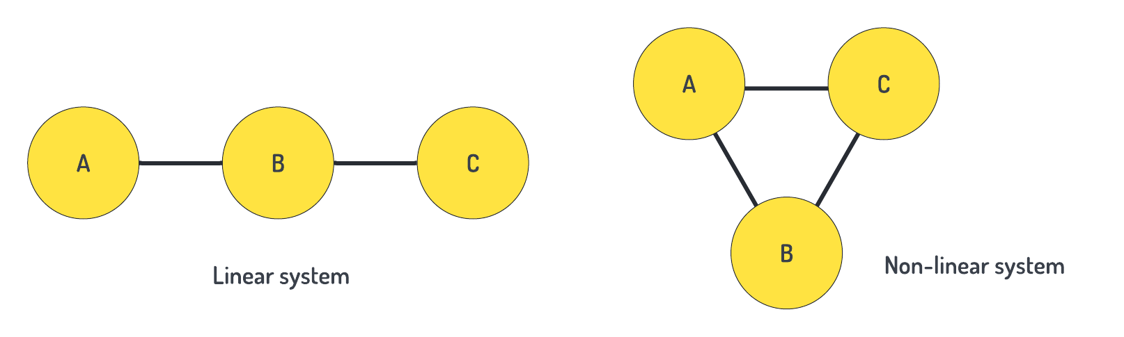
The level of maturity of a technology is then ranked based on its degree of novelty, uniqueness and current scope of application in the sector. The level of integration maturity (IML) may influence the overall technology maturity of interfacing systems, sub-systems or components. The Framework includes Technology Maturity Level (TML) adjustment factors which range from 0.5-1.0 for linear systems which comprise elements connected in series (see diagram below). This highlights that even if a technology is currently at a high TML, this will reduce when applied to a new interface and hence may require re-qualification. IMLs greater than 6 are deemed to be mature and hence do not influence the TML. Components which have multiple interfaces at different IMLs are classed as non-linear systems and particular methods exist for this system type. Adjustment factors can also be applied to Technology Readiness Levels (TRLs).
It is important to approach the maturity assessment conservatively to ensure a robust qualification plan is developed and all key risks addressed. It would be easy to say that a component is totally proven because of its previous usage in the offshore sector. However, this might then miss a particular load combination or risk specific to FOWT that later transpires to be an important failure mode.
If a technology is deemed to be mature, certain Classification Societies (e.g., Lloyds Register) allow the developer to 'fast-track' the process and achieve qualification.
Technology and Integration Maturity Level Calculator: Generic Mooring Connector
| Degree of novelty of technology | ||||
| Proven | Limited field history | New or unproven | ||
| Application area | Known | 1 | 2 | 3 |
| Limited knowledge | 2 | 3 | 4 | |
| New | 3 | 4 | 4 |
| IML description |
| 0: Interface not yet identified. |
| 1: Interface identified with sufficient detail to allow characterisation of the relationship. |
| 2: Some level of specificity to characterise the interaction. |
| 3: Technology compatibility allowing integration and interaction. |
| 4: Sufficient detail in the quality and assurance of the integration. |
| 5: Sufficient control to establish, manage and terminate the integration. |
| 6: The integrating technologies can accept, translate and structure information for the intended application. |
| 7: Integration verified and validated with sufficient detail to be actionable. |
| 8: Integration completed and mission qualified in the system environment. |
| 9: Integration mission proven. |
RISK ASSESSMENT
In order to focus qualification efforts, a quantitative failure analysis method, such as failure modes and effects criticality analysis (FMECA) can be used to assess threats and identify failure modes and their associated risks. As the name implies it considers the root causes, failure mechanisms and both localised and global effects (such as cascade failures). FMECA (and other TQ activities) can also be used to provide an early indication for the need to make design modifications. It is therefore prudent to carry out such analyses at early technology development phases in order to design out risks; potentially reducing the need for significant (and potentially costly) TQ activities further down the line.
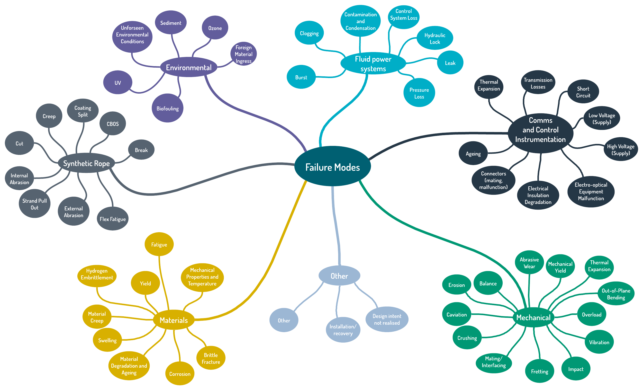
The first step is to assign potential failure modes, mechanism or causes and consequences to each technology element. Example failure modes that are relevant to mooring and anchoring systems are shown in the diagram below.
The risks associated with each failure mode are then categorised, depending on their impact and likelihood, the latter defined by the estimated probability (p) of occurrence during a one year period (% per annum). Failure probabilities may originate from numerical analyses of physical test data obtained in a laboratory environment or from field trials, be estimated from numerical models or based on failure databases. Caution must be exercised in applying the reliability performance of a component to different operating environments, duty cycles etc. The risk level and category of each risk score (the product of impact and likelihood scores) are used to ascertain the key strategies required to mitigate technological risk.
The granularity of information available to carry out risk and threat assessments, will depend on the technology development stage; qualitative approaches are likely to be made in the first instance, followed by quantitative assessments as more evidence (e.g., physical test data) is gathered during later development stages.
Risk Categorisation Calculator: Generic Mooring Connector
| Impact | ||
| Score | Rating | Meaning |
| 0 | None | None |
| 1 | Low | Insignificant impact |
| 2 | Low/Medium | Minor impact |
| 3 | Medium | Moderate impact |
| 4 | Medium/High | Major impact |
| 5 | High | Severe impact |
| Likelihood | |||
| Score | Rating | Meaning | Probability (% per annum) |
| 0 | None | Never | p < 0.01% |
| 1 | Low | Rarely occur | 0.01% < p < 0.1% |
| 2 | Low/Medium | Unlikely to occur | 0.1% < p < 1% |
| 3 | Medium | Possibly occur | 1% < p < 10% |
| 4 | Medium/High | Likely to occur | 10% < p < 50% |
| 5 | High | Almost certain | p > 50% |