

STAGE 3: QUALIFICATION PLAN DEVELOPMENT
The overall aim of Stage 3 is to develop a qualification strategy that addresses the risks and uncertainties, and hence reduce the likelihood of failure, according to the failure modes and risks identified in Stage 2. The main outcome is a Technology Qualification Plan (TQP) document, which details the outcomes of the System Decomposition and Technology and Risk Assessments carried out in the previous stage as well as the activities which will be carried out in order to obtain the evidence required to support the aims of the TQ programme.
For completeness, and to support later certification, it is good practice to include all elements of the system in the TQP, even those which have been deemed to have 'No new technical uncertainties' from a Technology Maturity standpoint or an 'Acceptable' risk category and hence require minimal TQ activities. Adopting this approach is also important in case any design modifications need to be made to a particular technology element which may impact other elements in the system, e.g., via interfaces, or a change to system operational ranges.
DEFINITION OF QUALIFICATION ACTIVITIES
The selection of qualification activities is likely to be driven by the need to generate robust evidence in a cost-effective way and is determined by the aims of the TQ programme and development stage. Technologies at low maturity levels tend to undergo laboratory-based and numerical analysis (i.e., virtual prototypes/Digital Twins and/or material testing and analysis), which in the first instance, focuses on reducing the largest uncertainties. It is likely that the Classification Society will require justification that the simulated environment is representative, as far as practicable, of the operating environment. At low maturity levels, the intended deployment environment may not be fully defined, or sufficient field data obtained.
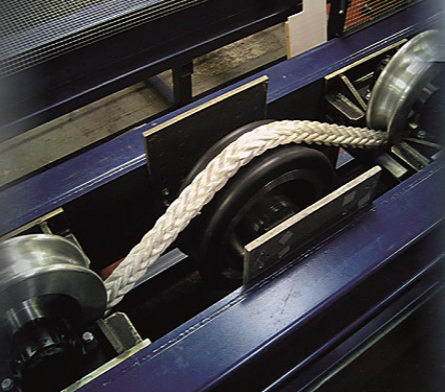
Generally, the parity between the simulated testing environment and real-world application increases with the progress of technology development. At later development stages, assembled components, subsystems and/or systems are likely to be subjected to more extensive testing and analysis programs, e.g., functional, cyclic and durability tests. To assist the decision making process radar graphs can be used to compare the implications of activities based on several metrics, e.g., activity complexity, duration, cost and probability of success. An example of equipment used to test rope abrasion at TTI Testing Ltd is shown on the right.
Qualification Activities Example: Generic Mooring Connector
|
The qualification plan for the generic mooring connector would include several desk-based and experimental activities, with the proposed activities referencing the system requirements outlined in Stage 1 and failure modes identified in the FMECA conducted in Stage 2. Example activities are listed in the tables below. |
| Experimental Qualification Activities | ||||||||||
| Failure mode | Relation to requirement | Purpose | Activity | Acceptance | Standard(s) | Limits (for test design) | Parameters | Accuracy | Analysis | Justification |
| Fatigue | Mooring connector has design life equivalent to other components on the FOWT | Determine mooring connectors fatigue life | Cyclic fatigue testing of the mooring connector at different loads | Creation of a S-N curve for the connector | DNV-RP-C203 - Fatigue Design of Offshore Steel Structures, DNV-OS-E302 Offshore mooring chain | Similar environmental conditions to deployment | Load (kN) | Failure to nearest 1000s cycles for a series of load ranges | Post-processing of cycles to failure for each load range | The test will help determine the design life of the mooring connector |
| Other Qualification Activities | ||||||
| Failure mode | Relation to requirement | Purpose | Activity | Evidence required | Success criteria | Standard(s) |
| Yield | Mooring connector is suitable strong enough to be deployed as part of a FOWT mooring system | Determine strength of the mooring connector | Conduct Finite Element Analysis | Finite Element Report detailing max load the mooring connector could support | Load capability of mooring connector are determined | DNV-OS-E302 Offshore mooring chain |
The interactive map below includes open water sites, component test facilities as well as wave and current tanks facilities in the UK and beyond which may have the capability to carry out the determined activities. In recent years particular facilities have provided access to technology developers in order to support qualification efforts in the offshore renewable energy sector via transnational funding programmes, for example the Marine Renewables Infrastructure Network (MaRINET2).
TECHNOLOGY QUALIFICATION PLAN CONTENT
Although Classification Societies have specific requirements for the content of the TQP, in broad terms most require the following aspects to be included: